Designing a print circuit board (PCB) for the aviation sector is very important to provide operational safety and success. With an aircraft system that faces extreme conditions such as vibration, temperature fluctuations, and electromagnetic disorders (EMI), each design element must meet strict requirements. Poor design can cause system failure, create risks for passengers and operational reliability. This guide outlines the principles for engineers and designers to develop flight PCBs that consistently meet the expectations of performance and safety.
This guide introduces eight rules for producing PCBs that meet special flight requirements. These principles help engineers and designers improve functionality, reduce failure rates, and meet industrial standards. Every rule discusses the important aspects of PCB design for flights to help achieve consistent results.
1. Meet industrial standards
To effectively combine industrial standards such as DO-254 and AS9100, identify their requirements during planning.
Save detailed notes about decisions made throughout the design process for audits and approval. Initial collaboration with the Certification Agency means that the design meets the obedience objectives, preventing expensive delays and revisions.
Entering compliance requirements at the beginning of the design process can save time and significant resources later. Documenting design decisions in accordance with this standard streamlins the certification process and reduce the risk of delay. Ignoring compliance can cause operational risks, including system failures or failures to achieve certification, resulting in an expensive redesign or project setbacks.
Following this specifications, designers produce PCBs that meet the high expectations of the aviation industry and situations include such electromagnetic interference controls.
2. Minimize electromagnetic disorders
An effective PCB design reduces EMI by combining strategies such as the right foundation, protector, and controlled impedance. Techniques such as separating high frequency components from low frequency and routing signal traces carefully help reduce interference. Layer or shield cover provides additional protection against external and internal sources. Controlled impedance is achieved through accurate traces and material selection, supporting consistent signal transmission.
Overcoming this during the design phase helps to avoid the problem, producing more reliable PCB flight electronics.
3. Use thermal management techniques
These techniques are an important aspect of flight PCB design, because excessive heat can damage components and reduce operational life. Aviation environment often involves high power electronics and limited cooling options, requires an efficient heat discipline strategy.
Thermal management techniques such as using heat sinks, thermal Vias, and high thermal conductivity materials help manage heat effectively. Thermal simulation during the design phase identifies potential hotspot and perfect the layout to increase heat distribution. Inserting copper pour or special thermal layers can improve thermal performance.
Take steps with initial thermal management reduce risk and support reliable performance in aviation electronics.
4. Make sure the vibration and resistance of shocks
Poor resistance to shocks and vibrations can cause component failure, which can endanger system performance. Designing for vibrations and shocks involves the placement of wise components, safe installation, and the use of special materials.
Flexible PCB is an effective solution for managing mechanical stress, because it can bend and flex without rupture. In addition, strengthening the solder connection and securing larger components with adhesive or brackets helps increase stability. Testing methods such as vibration tables and shock simulations validate design endurance in real world conditions, and prioritize vibrational resistance during design helps create reliable electronics.
5. Conduct an analysis of power integrity
PCB design requires power integrity to function, which means a strong power distribution network (PDN) is needed to maintain changes in voltage and sensitive electronics. The main techniques for increasing power integrity including designing the right power aircraft, strategically placed decoupling capacitors, and minimizing traces inductance. Using tools such as software analysis of power integrity helps identify potential problems at the beginning of the design process. This allows engineers to optimize power flow and overcome inefficiency before production. Managing power integrity effectively supports consistent functionality and reduces the risk of failure.
6. Design for signal integrity
Signal integrity is an important aspect of flight PCB design, especially for high -speed circuits where even small disturbances can cause damage. Poor signal quality causes crosstalk, signal reflection, and data errors, which cannot be accepted in the aviation system.
To increase signal integrity in a PCB, designers can optimize track routing by maintaining a consistent track width, using shorter signal pathways, and applying the right distance between traces. In addition, the use of land fields reduces noise and stabilizes signal transmissions. High frequency signals benefit from impedance matching to minimize signal loss. Overcoming this during the design phase helps achieve consistent performance and reliability in aviation electronics.
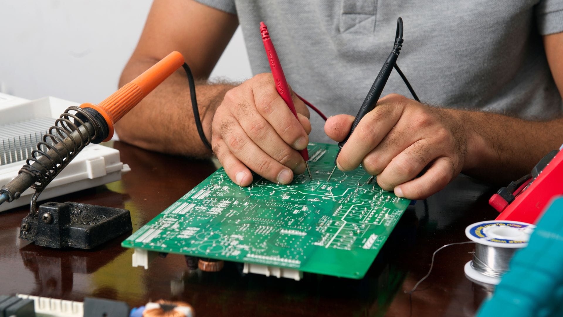
7. Perform strong testing
Validation of compliance is one way to ensure that PCB meets performance and reliability standards. These efforts, with processes such as thermal cycling to simulate extreme temperature conditions, vibration testing to evaluate mechanical stress security and electromagnetic compatibility test (EMC) to ensure boards operate without interference.
The prototype helps identify and solve design problems before production, allows engineers to improve the layout and validate real world functionality. Automatic testing tools further increase the efficiency and consistency of this process, provide reliable results that support the development of reliable flight PCBs. Flight PCB testing ensures that this council meets the special industrial requirements, strengthening their safety and performance in important applications.
8. Documents and trace changes
Maintaining documentation and tracking is very important, providing clear notes about design changes, material specifications, and test results. This supports compliance with industrial standards and simplifies problem solving when problems arise. Tools for managing design revisions, such as the control system version, allows the team to track change effectively and avoid inconsistency. Documentation also increases collaboration between engineers, producers, and other stakeholders, helping everyone work with the latest design iterations.
Tracking is very valuable to meet regulatory requirements and investigate every failure during the PCB’s life cycle. Maintenance of consistent notes supports long -term reliability and simplifies future updates or modifications.
The flight PCB design requires precision, compliance with standards, and attention to details. Still updated on the progress of PCB and purification design methods will help meet the changing sector demands. Altimex supports this effort with advanced PCB assembly services.
If you are looking for expert support on the flight PCB, contact Altimex today. Our experience and commitment to excellence can help you achieve extraordinary results for your next project.
Posting 8 Important Rules in PCB Design for Flights Appear First Time at Altimex.
Game Center
Game News
Review Film
Berita Olahraga
Lowongan Kerja
Berita Terkini
Berita Terbaru
Berita Teknologi
Seputar Teknologi
Berita Politik
Resep Masakan
Pendidikan
Berita Terkini
Berita Terkini
Berita Terkini
review anime
Gaming Center
Originally posted 2025-05-22 19:13:06.